Console
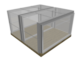
Construction of the frame sub-assembly is firmly underway. I will be doing some final prep work and welding the vertical sections together tonight. After that, I have a ridiculous number of holes to drill, tap, and countersink. I will also be priming and painting sections of the frame (I'm going with a slightly dark orange) as they are ready. After tonight's work, I will have a few interesting things to take pictures of, so expect those soon!Today, I spent a little time designing a console/enclosure for the electronics. I just had the idea to make something similar to a rack-style system. Basically the "rails" will be some small 1"x1" aluminum angle stock supported by some 1/2" aluminum square rods. The angle stock will be drilled and tapped to support one or two regular panel sizes.
The panels can then be made out of anything handy (acrylic sheets are my first choice). The panels will then have the cutouts for interface elements (buttons, LEDs, displays, etc), and I/O ports (power supply, motor output, sensor feedback, network/PC connections, etc).
In this initial idea, I have placed 6 acrylic panels on the top surface, each 9.25" x 6". The front and back surfaces have a total of 8 panels, each 9.25" x 5" (these dimensions might need to be normalized). The sides are simply covered by a plain sheet. The sides are intended to be very open and easy to access for continuous modification of the internal components without having to disassemble other subsystems. Individual panels should be designed to be removed entirely with (reasonable) wiring harnesses.
Here's a few of my planned panel modules:
- Power supply
-IEC male connector
- Machine I/O
- 4x RJ45 jacks (motor outputs)
- 1x RJ45 jack (axis limit switches)
- 1x RJ45 jack (home/calibration inputs, LED power)
- 2x RJ45 jacks (auxiliary jacks for new features)
- PC I/O
- USB B connector (ISP and debugging)
- DB9 (RS232)
- RJ45 connector (LAN)
- 3-axis manual control
- Joystick/directional control for X/Y control
- Up/Down buttons for Z control
- 3-axis status
- 3x LCD numeric displays (axis positions)
- Calibration overrides (zero buttons for each axis)
- Lathe module
- CW/CCW buttons (manual control)
- 1x LCD numeric display (axis position)
- Calibration override (zero button)
- Monitor display
- 128x64 or 128x128 simple LED monitor used for general system feedback
(After writing all this down, I'm very tempted to build each axis on its own panel.)
